Line of Sight Sensor
The LOS Sensor detects objects that have a visibility percentage above some threshold. It determines visibility by casting rays at the object and calculating the ratio that are obstructed. It is a Compound Sensor, meaning it requires another sensor as input. The Signals from the input sensor are each tested for line of sight.
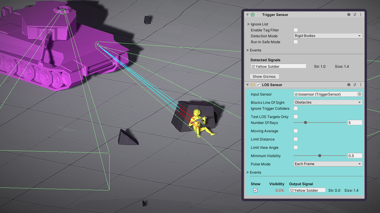
The LOS sensor determines the soldier has a visibility of 0% and therefore not detected
Output Signals
Object- Same as input SignalStrength- Visibility multiplied by the input Signal's strengthShape- Same as input Signal
The line of sight is calculated as soon as the input sensor detects a new Signal. It's updated each time the LOS Sensor is pulsed.
Test Points
Rays are cast at a number of test points on each signal to determine visibility. By default the points are randomly generated within the Shape of the signal. You can specify explicit test points by adding a LOSTargets component. If the sensor finds a LOSTargets component on the Signal.Object then it will use those test points instead.
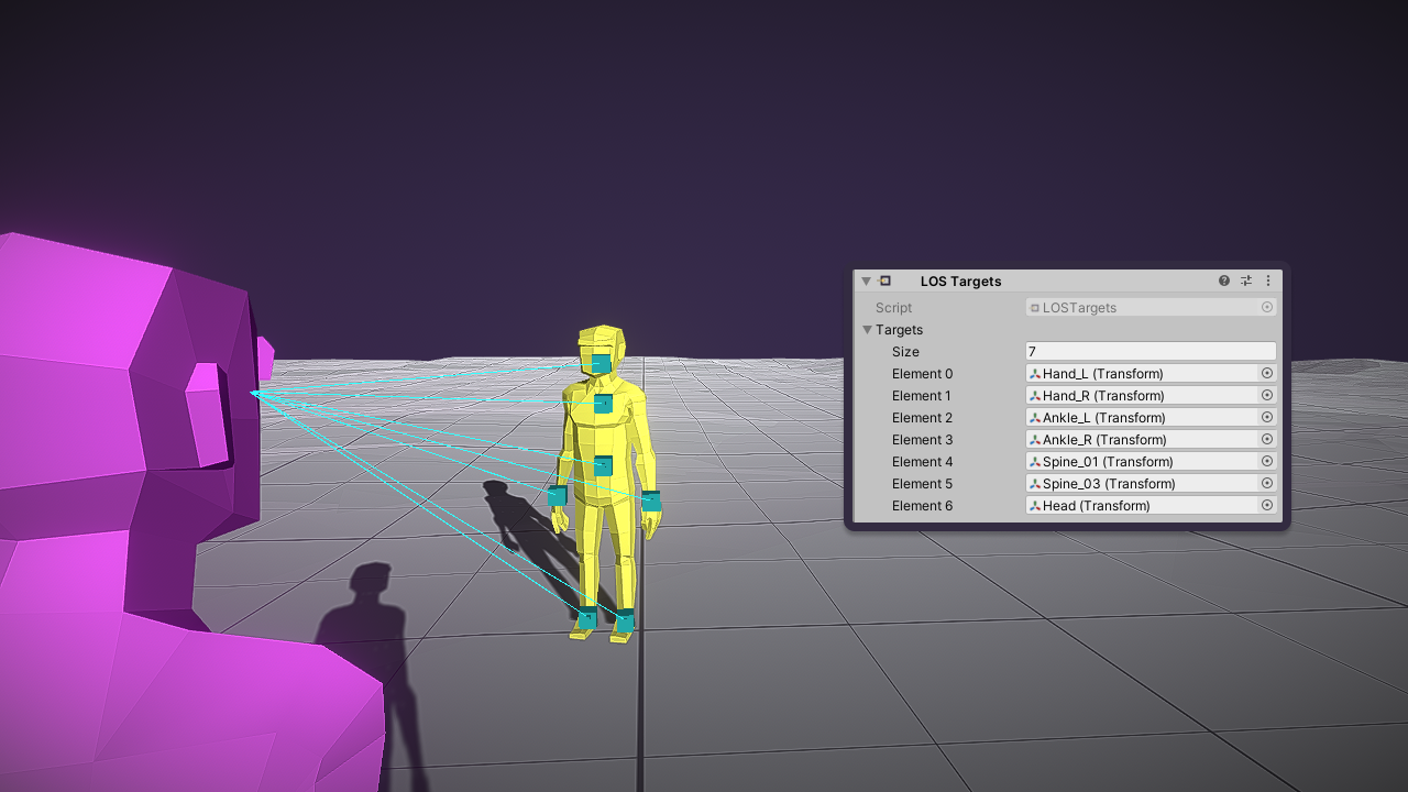
The yellow humanoid has a LOSTargets component specifying some of it's joints as test points
Configuration
Input Sensor
Can be any sensor deriving from Sensor, such as the Range Sensor or Trigger Sensor. It provides the Signals that will be tested for line of sight. To be detected an object must first be detected by the input sensor and then additionally pass the line of sight test of this sensor.
Raycasts
The Blocks Line Of Sight property configures which physics layers will block visibility. The number of raycasts performed when the sensor pulses is determined as follows:
- If the object has a
LOSTargetscomponent it will cast a ray for each test point on that component. - Otherwise it will cast the number specified by the Number Of Rays property.
If you enable the Test LOS Targets Only checkbox then the sensor will only work on objects with a LOSTargets component.
Moving Average
Enable this option to smooth the visibility scores over a number of pulses. It will reveal a new parameter called Window Size. The computed visibility of an object is its average visibility over a number of pulses equal to the Window Size. This is an effective way to eliminate sudden changes in visibility, even when the sensor tests with a single ray.
Field of View Limits
Distance Limits
When Limit Distance is enabled visibility is scaled by distance to the sensor. The following properties become available:
- Max Distance - Objects must be within this distance to be detected.
- Visibility By Distance - Determines how visibility is scaled by distance to the sensor. The default is Step meaning that visibilities are 0 when beyond the max range but are otherwise calculated normally. Other options include linear interpolation or custom curve.
Angle Limits
When Limit View Angle is enabled the visibility is scaled by angle to the sensor. The following properties become available:
- Max Horiz Angle - The max angle in the sensors horizontal field of view.
- max Vert Angle - The max angle in the sensors vertical field of view.
- Visibility By Horiz Angle - How is visibility scaled by a function of the horizontal angle.
- Visibility By Vert Angle - How is visibility scaled by a function of the vert angle.